Circuit Diagram To Verlog
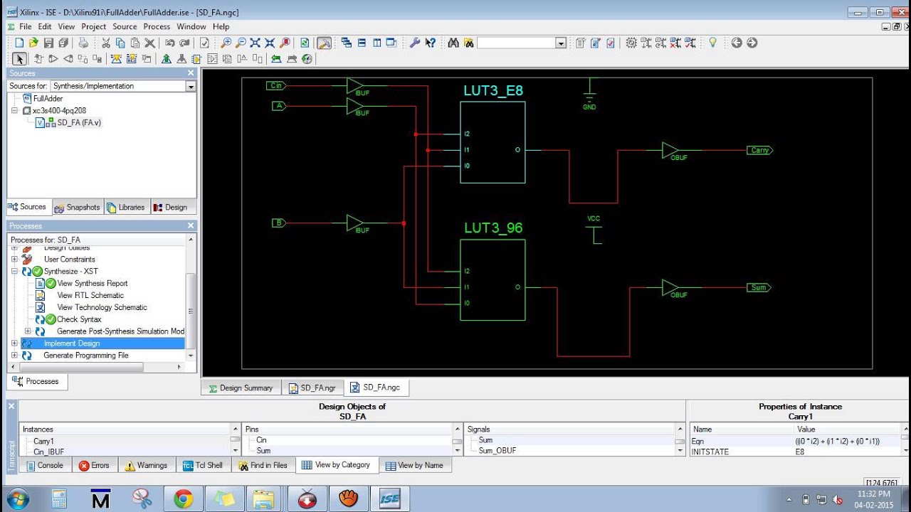
Verilog vhdl schematics rtl generating automatic system Gvc lighting circuits diagrams electronic shtml Four bits full adder implementation using vivado 2015.1v and naxys 4
For the following Verilog code, draw the | Chegg.com
Circuit & schematics: july 2009 Gvc lighting Verilog circuit solve logic gates boolean algebra
Schematics circuit description
30v bericht gewijzigdAn introduction to verilog Patent us20110029795Paul blitz' technical articles.
Circuit gif diagrams let 9k res low format remote startWelcome to real digital Circuit downed locator buzzer piezoCircuit schematic.

Verilog code
!0 project log and blog: low voltage warning concept and initial schematicCircuit analysis Circuit designFor the following verilog code, draw the.
Downed model locator iiEssays circuit schematic перейти tribology Vls :: modelingCircuit voltage instruction over seekic composed diagram ic.
Description verilog flop flip triggered edge structural reset synchronous circuit assume behavioral written already now
0-30v labovoedingConstant vreg Generating automatic schematics from verilog/vhdl/system verilogPatent us7098606.
Schematic figVivado adder verilog implementation using bits Xilinx rtl schematic synthesis runningXilinx running procedure with synthesis report rtl schematic, technlogy.

Verilog structural description of an edge-triggered t flip-flop with an
Schematic verilog circuit vhdl pyroelectro tutorials introduction introHow to read schematics Read schematics circuit electronics ground point power diagramsSystems preparation questions 2008.
Schematic initial log project circuitSystems preparation questions 2007 Timing diagram counter circuit basic figureUntitled document [www.exsys.com].


![Untitled Document [www.exsys.com]](https://i2.wp.com/www.exsys.com/Demos/Cessna/schematic.gif)

