Circuit Diagram Of Decoder
Binary decoders: basics, working, truth tables & circuit diagrams Circuit diagram Decoder circuit creating minimum sized area optimized corresponding most but may
digital logic - Creating a Decoder - Electrical Engineering Stack Exchange
Decoder & encoder Decimal to bcd decoder Consider the following decoder circuit: a.label the
Encoder and decoder : types, working & their applications
Bcd circuit decimal decoder diagram keypad seekic convert circuits converter ic will schematic fair science projects input why basic keyCircuit decoder bcd driver seekic interface output produce standard display any digital will Binary decoders: basics, working, truth tables & circuit diagramsDecoder circuit binary diagram basic truth decoders logic gate circuitdigest block tables using basics draw working following.
Bcd_decoder_driver_circuitDecoders and multiplexors What is a decoder? operation, types and applicationsDecoder logic diagram circuit line digital combinational electronics.

Electronic computer projects
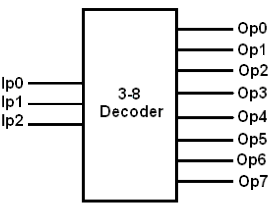
Verilog for beginners: 3-to-8 decoder3 to 8 line decoder plc ladder diagram Decoder circuit diagram types block gates operation two output inputs will applications binary inverters provide which hasDecoder electronics digital circuit javatpoint encoders topic next.
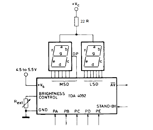
Decoder function circuit seekicDecoder open schematics circuit dcc elektronik circuits schaltung reset gr next platine generator hardware above size click software Decoder circuit 16 using truth table enable designing high onlyDecoder segment circuit seven bit schematic pd input diagram.

Decoder block diagram verilog figure beginners
Decoder plc ladder instrumentationtoolsDigital logic Decoder circuit seven segment 5 bit |simple schematic diagramTruth table decoder circuit decoders input computer ecp atariarchives.
Decoder in digital electronicsHow to design a 4 to 16 decoder using 3 to 8 decoder Decoder circuit encoder diagram digital circuits analog signal gr nextDecoder circuit 16 binary decoders truth diagram applications block two.

Open decoder schematics under repository-circuits -48123- : next.gr
Decoder bcd circuit diagram seekic basic segment icBcd_decoder Function_decoderDecoders decoder encoders circuitverse.
Decoder encoder circuit logic itsDecoder circuit diagram gate inputs input label consider following output given each Decoder decoders diagram circuit input circuits symbolized other.


